
This is a example code of how to set up Master <– Slave communication between two Codesys Runtime controllers. This example was made in Codesys version 3.5.16.20 . This example is intentionally set up as one-way communication, so you have to repeat the Master/Slave setup in both controllers or change the configuration to use R/W registers, but that is out of the scope for this example.
It is assumed that the reader of this article has a basic understanding of the MODBUS protocol. At least to understand the reasons for swapping around WORD data types and know about Big Ending, Little Endian, Most Significant Byte (MSB) and Least Significant Byte (LSB).
Naming convention in this example should be tailored to your project, to make it more easily disgustingly as to which controllers you have data from and to.
Network interface
Right-click on the Codesys controller and select “Add Device…” and add a Ethernet interface for the MODBUS protocol to work on.

Right-click the Ethernet interface and select “Add Device…” and add a MODBUS TCP Master if you are on the Master PLC or jump a few steps down and add a MODBUS TCP Slave Device to the Slave PLC.

Right-click the MODBUS TCP Master interface and select “Add Device…” and add a MODBUS TCP Slave.

Right-click the Ethernet interface and select “Add Device…” and add a MODBUS TCP Slave Device if you are on the Slave PLC.

The Ethernet interface on both Codesys controllers is to be configured. In this example I am going to use the same network interface as the controllers connect to the SCADA platform on. I have selected the first Ethernet port of the controllers, X000, br0, Eth0 it can have many different names.

On the Master PLC there is also a few settings for the MODBUS TCP Master and Slave interfaces. In this example I use a high timeout limit, adjust it to your application and most importantly, remember to tick on Auto-reconnect, you do not want to go online on each controller after a power-cut to re-enable MODBUS communication.

On the MODBUS TCP Slave interface we have to set up the IP-address of the Slave PLC, timeout and port. Port 502 is default.

Programming
A new type is made. It is a Union type called “Modbus2WordReal” and it will be used for data type conversion between WORD and REAL, with the freedom to switch around on WORD[0] and WORD[1] to account for MSB/LSB when communicating with various MODBUS devices. This new type is used in both Master and Slave PLC.

Some global variables are also needed in the GVL to make them accessible throughout the controllers programs. Only the From/Receive variables are used in this example.

I was a little more structured in the Slave PLC and added some comment structure to make it easier to read the code.

On the Master PLC the MODBUS TCP Slave has to be configured with the new variables in its Modbus Slave channel tab. Notice that the Channel names I gave them corresponds to the READ Offset, that is written out in hex, 16#0200 = 512 written in decimal in the editor when adding new channels. Read Input Registers /Function Code 04) is used.

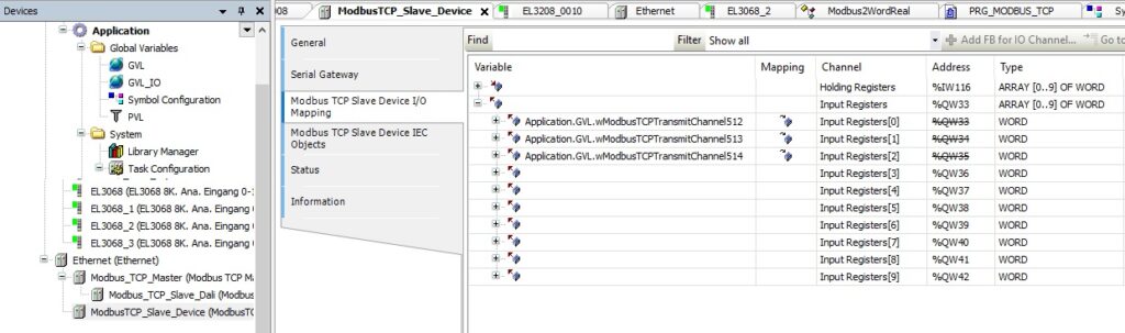
On the Slave PLC we have to set up the corresponding registers for them to match between Master and Slave. The MODBUS TCP Slave Device has settings for defining number of registers and offset on start addresses.

MODBUS TCP Slave Device I/O Mapping shows why I named the variables as I did, to match the registers used.
The program of the Master PLC is a simple WORD_AS_BIT conversion from the received register 512 and it is converted into 16 single bits that can be used in your other programs in the controller. For register 513+514, notice how the WORD conversion to REAL and possibility of swapping the two WORD around is done with the Union data type. Here it is just a local instance of the PRG_MODBUS_TCP program as I would add the REAL variable on the output of the MOVE block.

The program of the Slave PLC is a simple BIT_AS_WORD conversion from the 16 single bits that can be used in your other programs in the controller to be transmitted to register 512. For register 513+514, notice how the possibility of swapping the two WORD around is done with the Union data type. Here it is just a local instance of the PRG_MODBUS_TCP program.

Test of MODBUS TCP communication
A small test program was written in the Slave PLC PRG_MODBUS_TCP program to generate a alternating switching bit and a analog value that kept changing, here with a triangle waveform 0 to 1000 over 60 seconds. Notice how the REAL value is written into the Union using the .AsReal attribute to write into the correct part of it.
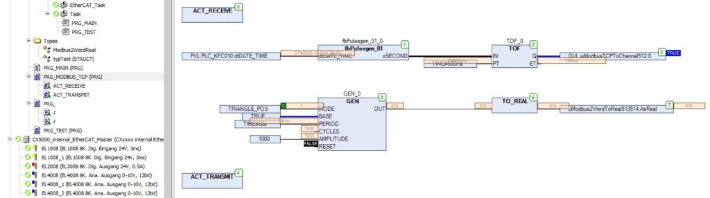
Looking at the transmitting program, it can be seen that the REAL value is now represented as two WORD that is transmitted in each their register.

The result of our hard work is now seen in the Master PLC that receives the data perfectly fine and the transmitted WORD registers is translated into BIT and REAL values to be used.

MODBUS TCP communication is simple and easy to configure in Codesys Development System V3.
Discover more from SCADA, PLC and Automation Engineering
Subscribe to get the latest posts sent to your email.
Good morning, I really liked your information, you will not have an example to download, thank you very much